Air handling terminal unit
UTNA Platinum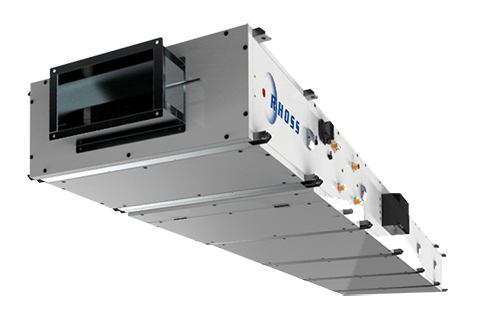
Modular ductable air handling terminal units.
Features


Key features
Brushless EC fan IE5 efficiency
Horizontal or vertical installation
ISO Coarse Filter 55% (G4) Airsuite Biocide
ePM1 filter 50% (F7)
Description
Construction features
• Terminal air handling unit: with modular units for horizontal or vertical installation (013-050) with ducting.
• Structure with double wall sandwich type freestanding panelling, 30mm-thick with closed cell expanded polyurethane insulation with high soundproofing and thermal insulation capacity.
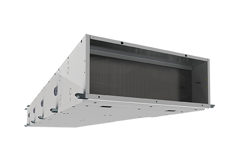
• Routine machine maintenance from the bottom (for the horizontal version with installation in false ceiling or hanging from ceiling) or frontally (for the vertical version) with removable panels.
• Coil module BA (horizontal) / coil module BAV (vertical up to size 050) including: standard ISO Coarse Filter 55% (G4), All filters are supplied complete with differential pressure switch to signal filter clogging condition in compliance with European regulation no. 1253/2014.
Finned coil heat exchanger, with copper pipes and 2 rows of aluminium fins for heating or reheating only and 4-6 rows for cooling and/or heating with right or left connections to be selected with order. Condensate drain pan in aluminium both for horizontal BA4R and BA6R versions and vertical BAV4R and BAV6R versions.
• SV fan module complete with EC Brushless plenum centrifugal fan with single intake directly coupled to electric motor efficiency class IE5. Static and dynamic balancing of the entire assembly, built in accordance with DIN ISO standard 1940. G6.3 balancing grade. Standard control of the rotation speed via special 0-10V analogue input. Electrical connection panel fitted as standard complete with disconnect switch, protection fuses and connecting terminal block.
Factory fitted accessories
• AIRSUITE G4- Iso Coarse Filter 55% (ISO 16890) G4 (EN 779) Airsuite with biocide capacity
• F7 - Fine dust filter Iso ePM1 50% ( ISO 16890) F7 (EN 779)
• SG - Optional polypropylene drop separator at low load losses.
• TAG - Optional antifreeze thermostat.
Accessory modules
• PMA - Intake/outlet plenum with pre-cut side outlets.
• SIL - Plenum with absorbent cartridge silencer to be placed on delivery or intake.
• MUV-PRV - Plenum with steam humidifier and external electric generator.
• BE - Additional electrical coil for connection to channel.
Separately supplied accessories
• KSG - Polypropylene drop separator at low load losses (only for BA).
• KTAG - Antifreeze thermostat (only for BA).
• KSER - Kit in combination with PMA consisting of: damper with aluminium blades and frame, fitted with seal gasket, certified class 2 according to En 1751 for fresh air (max 30%) or recirculated air and a fastening panel to PMA module. The damper is sized for treating up to 100% of the UTNA air flow rate and may be positioned at the front, top or bottom of the PMA.
• KMS - Manual control for KSER damper.
• KB2R - Separately supplied additional reheat coil.
Controls
• KPTZ - Potentiometer for wall mounting installation, for manual fan speed control.
• KTVDIM - Electronic control panel with display, for semi-recessed wall installation, including ON/OFF button, MODE, 3 Speeds+AUTO, SETPOINT change; auxiliary contacts to control ON/OFF valve in 2-pipe and 4-pipe systems; summer/winter switching; manual/automatic/from contact; continuous/thermostat ventilation; configurable digital inputs (SCR, ECO, SIC, ALARM), weekly time bands control, complete with RS485 resident serial interface (Modbus RTU protocol).
• KRCA1 - Electronic control panel with display, for semi-recessed wall installation, including ON/OFF button, MODE, 2 Speeds, SETPOINT change; summer/winter switching with button or remote digital input; continuous ventilation, weekly time bands control room probe; 3 analogue outputs to control modulating fan, 1 or 2 modulating valves in 2-pipe or 4-pipe systems, modulating damper; 1 auxiliary contact to control on/off electrical resistance (1 stage) in 2-pipe systems + electrical resistance; 2 configurable digital inputs and 2 configurable analogue inputs. Compete with RS485 resident serial interface (Modbus RTU protocol).
• KPAU - Humidistat panel for PRV steam producer control.
• FULL CONTROL- for a description of these controls, please refer to the relevant page
Full Controls
• KRFCS - Electrical panel complete with: DDC programmable microprocessor regulator. BMS interfacing Integrated as standard with Modbus RTU protocol, main disconnecting switch, relay to control various users, terminal blocks for quick connection of all machine components, auxiliary circuit supply with suitable transformer 230/12-24V.
USER PANELS (for KRFCS)
• KHMIG -Interface terminal with black monochrome graphic display with LED backlighting.
• KHMIR - Interface terminal complete with integrated room temperature probe with black monochrome graphic display with LED backlighting.
• KCW - White decorative plate for control panel.
• KCB - Black decorative plate for control panel.
• KWMS - Wall mounting installation support for control panel.
Valves and actuators
• KV3V - PN40 Mixer/diverter 3-way regulation ball valves, female threaded hydraulic connections.
• KV2V - PN40 2-way regulation ball valves, female threaded hydraulic connections.
• KVMM - Actuator for ball regulation valves with modulating control 0/10 Vdc 24 Vac power supply.
• KV0M - Actuator for 230V On/Off valves.
• KDMA-S - Actuator for modulating damper 0-10V 24V with spring return.
• KDMA - Actuator for modulating damper 0-10V 24V without spring return.
• KDOA - Actuator for ON/OFF damper with spring return.
All the probes, actuators and valves on the Full Control section are also available.
Technical data
| UTNAP MODEL | 13 | 25 | 35 | 50 | 75 | 90 | 120 | ||||
| ❷ | Coil thermal power Only hot | BA 2R/BAV 2R | kW | 4,9 | 8,4 | 11,7 | 16,8 | 25,1 | 32,8 | 39,1 | |
| ❶ | Cooling capacity (total heat) | BA/BAV 4R | kW | 6,4 | 11,1 | 14,6 | 21,3 | 31,9 | 45,2 | 53,6 | |
| ❶ | Cooling capacity (sensitive heat) | BA/BAV 4R | kW | 5 | 8,9 | 12 | 17,2 | 25,9 | 34,6 | 42,4 | |
| ❷ | Heating capacity | BA/BAV 4R | kW | 7,6 | 13,6 | 18,4 | 26,5 | 39,7 | 52,3 | 64,4 | |
| ❶ | Cooling capacity (total heat) | BA/BAV 6R | kW | 8,1 | 14,9 | 20,2 | 27,5 | 41,2 | 56,8 | 68,9 | |
| ❶ | Cooling capacity (sensitive heat) | BA/BAV 6R | kW | 5,9 | 11 | 15,1 | 21 | 31,5 | 41,4 | 51,6 | |
| ❷ | Heating capacity | BA/BAV 6R | kW | 9,1 | 16,6 | 22,8 | 32,2 | 48,3 | 62,1 | 78,2 | |
| ❸ | Electrical resistance power | BE | kW | 3 | 6 | 9 | 13 | 17 | 24 | 24 | |
| Electrical supply | BE | V-ph-Hz | 230-1-50 | 400-3-50 | 400-3-50 | 400-3-50 | 400-3-50 | 400-3-50 | 400-3-50 | ||
| Adjustment type | BE | 1 step | 1 step | 1 step | 2 step | 2 step | 2 step | 2 step | |||
| Erp classification | SV | UVU | UVU | UVU | UVU | UVU | UVU | UVU | |||
| Fans | SV | n° | 1 | 2 | 2 | 2 | 2 | 2 | 2 | ||
| Adjustment type | SV | EC brushless/ 0-10V | EC brushless/ 0-10V | EC brushless/ 0-10V | EC brushless/ 0-10V | EC brushless/ 0-10V | EC brushless/ 0-10V | EC brushless/ 0-10V | |||
| ❹ | Air flow rate | NOM | m³/h | 1300 | 2500 | 3500 | 5000 | 7500 | 9000 | 12000 | |
| MIN | m³/h | 800 | 1100 | 1500 | 2100 | 3100 | 5000 | 5000 | |||
| MAX | m³/h | 2100 | 3700 | 4800 | 6700 | 10500 | 14400 | 15500 | |||
| ❹ | Useful static head. | NOM | Pa | 300 | 300 | 300 | 300 | 300 | 300 | 300 | |
| Electrical supply | SV | V-ph-Hz | 230-1-50 | 230-1-50 | 230-1-50 | 230-1-50 | 400-3-50 | 400-3-50 | 400-3-50 | ||
| ❺ | Irradiated sound power | SV | dB(A) | 53 | 57 | 61 | 60 | 63 | 62 | 65 | |
| ❺ | Intake sound power | dB(A) | 61 | 65 | 68 | 67 | 70 | 70 | 73 | ||
| ❺ | Delivery sound power | SV | dB(A) | 71 | 74 | 78 | 78 | 81 | 80 | 83 | |
| ❹ | SFP Int (Erp 2018 | ||||||||||
| Filter class EN779 | G4/F7 | G4/F7 | G4/F7 | G4/F7 | G4/F7 | G4/F7 | G4/F7 | ||||
| PRV Maximum steam production | PRV | Kg/h | 3 | 5 | 5 | 8 | 10 | 15 | 18 | ||
| Electrical supply | PRV | V-ph-Hz | 230-1-50 | 230-1-50 | 230-1-50 | 400-3-50 | 400-3-50 | 400-3-50 | 400-3-50 | ||
| DIMENSIONS AND WEIGHTS | 13 | 25 | 35 | 50 | 75 | 90 | 120 | ||||
| L – Width | mm | 945 | 1245 | 1545 | 1645 | 1645 | 2045 | 2045 | |||
| H – Height | mm | 387 | 387 | 387 | 504 | 687 | 837 | 837 | |||
| SV – Depth | mm | 750 | 750 | 750 | 750 | 750 | 750 | 750 | |||
| BA – Depth | mm | 750 | 750 | 750 | 750 | 750 | 750 | 750 | |||
| PMA – Depth | mm | 480 | 480 | 480 | 596 | 780 | 931 | 931 | |||
| BE – Depth | mm | 270 | 270 | 270 | 270 | 270 | 270 | 270 | |||
| MUV – Depth | mm | 750 | 750 | 750 | 750 | 750 | 750 | 750 | |||
| SIL – Depth | mm | 750 | 750 | 750 | 750 | 750 | 750 | 750 | |||
| BAV – Height | mm | 812 | 812 | 862 | 962 | - | - | - | |||
| SV Weight | kg | 53 | 60 | 67 | 88 | 94 | 132 | 142 | |||
| ❻ | BA Empty weight | kg | 67 | 90 | 105 | 112 | 136 | 191 | 191 | ||
| ❻ | BAV Empty weight | kg | 62 | 78 | 95 | 121 | - | - | - | ||
| PMA Weight | kg | 22 | 27 | 32 | 40 | 51 | 70 | 70 | |||
| BE Weight | kg | 18,5 | 23 | 27,5 | 32 | 34 | 62,5 | 62,5 | |||
| MUV Weight | kg | 28 | 34 | 40 | 44 | 47 | 58 | 58 | |||
| SIL Weight | kg | 34 | 44 | 51 | 58 | 70 | 91 | 91 |
- Data at the following conditions:
- ❶ Air T in 26°C D.B.; 18.6°C W.B. (50% R.H.); water T in 7°C with Δt 5°C; nominal air flow rate.
- ❷ Air T in 20°C D.B.; 13.7°C W.B. (50% R.H.); water T in 40°C with Δt 5°C; nominal air flow rate.
- ❸ Air T in 20°C D.B.; 13.7°C W.B. (50% R.H.); nominal air flow rate.
- ❹ Air T in 20°C D.B.; 13.7°C W.B. (50% R.H.); nominal air flow rate; 4-row coil BA/BAV 4R; clean type F7 filter.
- ❺ Of SV only with work point at nominal air flow rate; and total head calculated in configuration: 4-row coil BA/BAV 4R; clean type F7 filter; available static 300 Pa. In accordance with EN ISO 11546-2.
- ❻ Weight considered for a BA structure+filter+BA6R coil+BA2R coil+SG droplet separator+TAG antifreeze thermostat configuration. For other configuration weights, please refer to Rhoss 2up to Date” selection software
Manuals
To view all the documents, log in to the reserved area
Technical notes
To view all the documents, log in to the reserved area
Documents
To view all the documents, log in to the reserved area
Request information about this product
Find a reseller in your area for a customized offer on Rhoss air conditioning solutions.