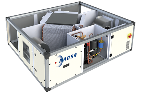
Heat recovery unit
UTNR-HPFresh air terminal units with two-stage heat recovery unit.
Features


Key features
Combined crossed flow and active thermodynamic heat recovery
Standard air filter with G4 efficiency
Integrated electronics
Description
Construction features
• Recovery unit:
- First stage of the crossed flow air-air static heat recovery with aluminium heat exchanger plates; lower condensate drain pan along the entire heat treatment zone.
- Second stage of the active thermodynamic heat recovery unit with heat pump cooling circuit (with R410A gas) consisting of hermetic compressor (rotary or scroll type depending on the size of the machine), evaporating and condensing coils with copper pipes and continuous aluminium fins, electronic expansion valve, liquid separator and receiver, 4-way valve for cycle inversion, high and low pressure switches, Freon filter and liquid indicator.
• Fans: fresh air inlet and exhaust EC Brushless type with a directly coupled electric motor. Fan unit installed on anti-vibration mountings to prevent the transmission of vibration.
• Structure and panels: frame made with extruded aluminium profile, Anticorodal 63 alloy, with preloaded nylon angular joints. Sandwich buffer panels, 23 mm thick, made internally with galvanised sheet steel and externally with galvanised pre-painted sheet steel (RAL 9002), with thermal and acoustic insulation made of injected polyurethane, with a density of 45 kg/m3.
• Filtering section: consisting of two class G4 filters (one on the fresh air intake and one on the ambient inlet), both can be removed from the bottom and side.
• Electrical panel: with integrated adjustment and power; NTC temperature probes on both the delivery and return air circuits; micro-processor electronic control for automatic room temperature management, winter/summer switch and thawing cycles; remote control of panel up to 20 m from the unit,
Versions
Available orientation:
• UTNR-HP 01, 02 – Heat recovery unit with cross-flow and active thermodynamic double heat exchanger with 01 or 02 orientation (right connection side) or 01s or 02s (left connection side).
The selected orientation must be specified to process the job order.
Installation
• EXT - Protective roof for outdoor installation.
Factory fitted accessories
• BER - Internally installed filament type reheating electrical resistance, complete with safety thermostats and control relays. 230/1/50 single-phase for models 035-150. 400/3/50 three-phase for models 230-450.
• BEP - Internally installed filament type reheating electrical coil, complete with safety thermostats and control relays. 230/1/50 single-phase for models 035-150. 400/3/50 three-phase for models 230-450.
• PF - Differential pressure switch alerting to dirty filter, installed on intake filter.
• ATG - Antifreeze thermostat installed downstream of the water coil.
• EG4PF - G4 outdoor air filter with differential pressure switch.
• ERG4PF - G4 outdoor air filter and G4 return air with differential pressure switch.
• EF7 - F7 ePM1 70% outdoor air filter
• ERF7 - F7 ePM1 70% outdoor and return air filter.
• EG7PF - F7 ePM1 70% outdoor air filter with differential pressure switch.
• ERF7PF - F7 ePM1 70% outdoor and return air filter with differential pressure switch.
Separately supplied accessories
• KSBFR - Section containing hot/cold water coil for reheat or recool, placed outside the machine in front of the intake vent. Includes a stainless steel condensate drain pan with drain connection from the bottom.
• KSBFR + ATG - Hot/cold water coil section with mounted antifreeze thermostat.
• KV2V ON/OFF - 2 way valve kit with On/Off servo-control.
• KV3V ON/OFF - 3 way valve kit with On/Off servo-control.
• KSRE230 - Regulation damper consisting of a galvanised sheet steel frame with adjustable fins, equipped with 230V ON/OFF servo-control.
• KSME230R - Regulation damper consisting of a galvanised sheet steel frame with adjustable fins, equipped with 230V ON/OFF servo-control with spring return.
• KSSC - Duct silencer with wool baffles covered with glass fibre and micro-stretched sheet steel.
• KRMS - 3-damper section for operation with outdoor air at low temperature up to -20°C, with modulating servo-controls.
Controls supplied separately
• KTUP - Additional user terminal, with remote control up to 50 m, for wall mounting.
• KSCMB - Modbus serial sheet.
Technical data
| UTNR-HP MODEL | 35 | 60 | 100 | 150 | 230 | 320 | 450 | ||||
| Nominal air flow rate | m³/h | 350 | 600 | 1000 | 1500 | 2300 | 3200 | 4500 | |||
| Available delivery static pressure | Pa | 165 | 170 | 195 | 155 | 155 | 185 | 175 | |||
| Available return static pressure | Pa | 140 | 100 | 140 | 95 | 95 | 115 | 110 | |||
| ❶ | Sound pressure level | db (A) | 59/47/52 | 64/50/55 | 62/49/54 | 67/54/57 | 65/51/59 | 68/54/59 | 70/56/59 | ||
| Max available delivery static pressure – E Brushless Version | Pa | 270 | 285 | 295 | 290 | 365 | 265 | 270 | |||
| Max available return static pressure – E Brushless Version | Pa | 245 | 215 | 240 | 230 | 305 | 195 | 205 | |||
| FUNCTIONAL LIMITS | |||||||||||
| ❷ | Standard configuration winter limit operating conditions | °C / % | MIN -10°C OUT & MIN 19°C 50% IN | ||||||||
| ❷ | Winter limit operating conditions with KRMS accessory | °C / % | MIN -20°C OUT & MIN 19°C 50% IN | ||||||||
| Summer limit operating conditions | °C / % | MAX 38°C 50% OUT & MAX 27°C IN | |||||||||
| Flow rate variation field | % | -10/10 | |||||||||
| ELECTRICAL SPECIFICATIONS | |||||||||||
| Electrical supply | V/ph/Hz | 230/1/50 | 230/1/50 | 230/1/50 | 230/1/50 | 400/3/50 | 400/3/50 | 400/3/50 | |||
| Max. absorption | A | 5,3 | 9 | 13,2 | 20,2 | 10 | 15,4 | 16,4 | |||
| ❸ | PERFORMANCE IN HEATING MODE | 35 | 60 | 100 | 150 | 230 | 320 | 450 | |||
| Static recovery efficiency | % | 62 | 51 | 50 | 50 | 50 | 50 | 50 | |||
| Active recovery | W | 1740 | 2960 | 5010 | 7690 | 11090 | 16300 | 17300 | |||
| Total power | W | 3580 | 5790 | 9410 | 14390 | 21190 | 30260 | 36010 | |||
| Treated air temperature | °C | 24 | 23 | 22 | 22 | 22 | 22 | 18 | |||
| ❹ | Overall COP | W/W | 10,9 | 9,6 | 9,22 | 8,64 | 8,9 | 9,9 | 12,6 | ||
| ❺ | PERFORMANCE IN COOLING MODE | ||||||||||
| Static recovery efficiency | % | 56 | 50 | 50 | 50 | 50 | 50 | 49 | |||
| Active recovery | W | 1810 | 2860 | 4890 | 7270 | 10580 | 15310 | 16990 | |||
| Total power | W | 2210 | 3450 | 5840 | 8720 | 12830 | 18390 | 21440 | |||
| Treated air temperature | °C | 19 | 20 | 20 | 20 | 20 | 20 | 21 | |||
| ❹ | Overall EER | W/W | 4,2 | 3,9 | 4,2 | 3,9 | 3,9 | 4,1 | 5,01 | ||
| ACCESSORIES | |||||||||||
| BEP-BER Rated power | W | 1500 | 1500 | 3000 | 3000 | 6000 | 9000 | 12000 | |||
| BEP-BER no. of stages | n° | 1 | 1 | 1 | 1 | 3 | 3 | 3 | |||
| ❻ | KSBFR-Thermal yield | W | 2000 | 3100 | 4800 | 7800 | 11800 | 15300 | 21000 | ||
| ❼ | THAIY-Cooling capacity | W | 1200 | 1400 | 2900 | 4400 | 7900 | 9100 | 13100 | ||
| DIMENSIONS AND WEIGHTS | |||||||||||
| Length | mm | 1540 | 1540 | 1840 | 1840 | 2040 | 2040 | 2240 | |||
| Height | mm | 370 | 370 | 410 | 500 | 550 | 650 | 710 | |||
| Depth | mm | 1240 | 1240 | 1440 | 1440 | 1690 | 1690 | 1890 | |||
| Weight | Kg | 122 | 125 | 185 | 228 | 267 | 281 | 329 |
- Data at the following conditions:
- ❶ Sound pressure level assessed at 1 m from: permanent ducted socket/intake socket/compressor compartment. Generally, the operating noise level differs from the indicated values depending on the operating conditions, reflected noise and peripheral noise.
- ❷ Referred to the nominal flow rate.
- ❸ Outdoor air -5°C UR 80%; ambient air 20°C UR 50%.
- ❹ Excluding adsorbed power for ventilation.
- ❺ Outdoor air 32°C RH 50%; ambient air 26°C UR 50%.
- ❻ Incoming air 20°C; water in/out 45/40°C
- ❼ Incoming air 21°C-75% UR; water in/out 7/12°C
Manuals
To view all the documents, log in to the reserved area
Technical notes
To view all the documents, log in to the reserved area
Documents
To view all the documents, log in to the reserved area
Images
Request information about this product
Find a reseller in your area for a customized offer on Rhoss air conditioning solutions.