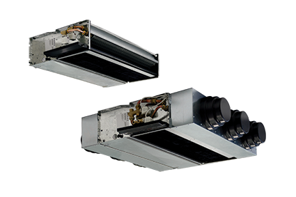
Ducted fan coils
YARDY-DUCT2Ducted fan coils for recessed horizontal or vertical installation.
Features


Key features
APP for control and scheduling via smartphone
Air’Suite biocide filter for healthier and cleaner air in indoor environments
New touch controls
Enhanced performance with 4-row coil
6-speed ductable version
Horizontal and vertical installation
Pre-fitted accessories and controls
Description
Construction features
• Heat exchanger: with finned coil with left side connections reversible to the right.
• Centrifugal fan: 6 speeds connected to the terminal block.
• Structure: made of galvanised sheet steel complete with a natural condensate drain pan and regenerable filter.
Versions
• CXP - Recessed unit for horizontal or vertical installation (with lower return and upper delivery).
Construction set-ups
Type of unit
2T - Single main coil.
4T - Double main coil and additional.
ACCESSORIES
➔❖ Additional water heating coil for 4-pipe systems.
➔❖ Electrical resistance.
➔❖ 2-way ON/OFF electrovalves for 2 and 4-pipe systems.
➔❖ 3-way ON/OFF electrovalves for 2 and 4-pipe systems.
➔❖ 4-way ON/OFF electrovalves for 4-pipe systems with single main coil.
➔❖ Auxiliary condensate drain pan.
➔❖ Air'Suite biocide filter.
❖ Electrical box for connection terminal block.
❖ Air inlet flange: Ø10cm or Ø12cm.
➔ Flanged frame for connection to intake or delivery duct.
➔ Frame with Air'Suite biocide filter (G2) that can be extracted in any direction.
➔ Delivery straight fitting.
➔ 90° delivery and inlet fitting.
➔ Telescopic outlet/inlet fitting.
➔ Inlet grille with filter.
➔ Delivery grille.
➔ Formwork for recessed wall or false ceiling installation.
➔ Aesthetic panel for formwork, with air inlet grille for wall mounting or ceiling installation.
➔ Delivery nozzle made of aluminium, with a double row of adjustable fins.
➔ Anti-vibration fitting for delivery/inlet duct connection.
➔ Intake/outlet plenum with round nozzles.
CONTROLS
STANDARD controls
For wall mounting installation
➔ Panel with speed and summer/winter switch.
➔ Panel with room thermostat, summer/winter switch, speed switch, ON/OFF valve control and electrical resistance.
➔ Minimum temperature thermostat (for installation on machine).
➔ Electronic panel with automatic summer/winter switching for 2-pipe systems.
➔ Electronic panel with automatic summer/winter switching and automatic speed adjustment for 2-pipe systems with electrical resistance or 4-pipe systems.
➔ Interface board to control up to 4 fan coils (for on board installation).
➔ Electronic panel with display and RS485 serial interface, semi-recessed in wall.
Advanced LIT-TOUCH controls
➔ Flush LIT-Touch control panel in glossy black or pearl white for wall mounting installation.
➔ Wall mounted LIT-Touch remote control and receiver with air temperature probe and operation LED.
For on board installation
➔❖ LIT-Touch electronic control for 2-pipe systems, with 2 pipes with electrical resistance or 4 pipes, complete with a minimum water temperature probe, ON/OFF valve control and integrated master/slave function up to a total of 15 units.
➔❖ Additional board with 2 digital outputs that can be configured.
➔❖ On board air temperature probe.
➔ Wi-Fi gateway for Rhoss TEMA APP and LIT-Touch control
➔❖ RS485 serial board for serial communication with other devices (Modbus RTU protocol).
Key: ❖ Factory fitted
➔ Supplied separately
* Previous name
Technical data
| YARDY-DUCT2 CXP | 40 | 48 | 60 | 74 | 80 | 88 | ||||||||||
| ❶ | Total cooling capacity [EN1397] | VI | kW | 1,9 | E | 2,22 | E | 3,47 | E | 4,43 | E | 4,83 | E | 5,69 | E | |
| V | kW | 1,76 | E | 2,06 | E | 3,33 | 4,26 | 4,61 | 5,53 | |||||||
| IV | kW | 1,5 | 1,69 | 3,18 | E | 4 | E | 4,38 | E | 5,42 | E | |||||
| III | kW | 1,35 | E | 1,57 | E | 3,01 | 3,78 | 4,17 | 5,2 | |||||||
| II | kW | 1,24 | 1,44 | 2,65 | E | 3,41 | E | 3,91 | E | 4,94 | E | |||||
| I | kW | 1,07 | 1,25 | 2,42 | 3,14 | 3,86 | 4,8 | |||||||||
| ❷ | Heating capacity (45°C) [EN1397] | VI | kW | 2,1 | E | 2,15 | E | 4,11 | E | 4,18 | E | 5,77 | E | 6,12 | E | |
| V | kW | 1,9 | E | 1,97 | E | 3,92 | 3,98 | 5,62 | 5,8 | |||||||
| IV | kW | 1,53 | 1,59 | 3,69 | E | 3,75 | E | 5,51 | E | 5,74 | E | |||||
| III | kW | 1,4 | E | 1,46 | E | 3,49 | 3,54 | 5,3 | 5,45 | |||||||
| II | kW | 1,27 | 1,33 | 3,21 | E | 3,26 | E | 4,78 | E | 5,1 | E | |||||
| I | kW | 1,11 | 1,16 | 2,94 | 2,98 | 4,61 | 5,06 | |||||||||
| ❸ | Heating capacity (50°C) | VI | kW | 2,44 | E | 2,53 | E | 4,74 | E | 4,98 | E | 6,68 | E | 7,16 | E | |
| V | kW | 2,21 | E | 2,32 | E | 4,52 | 4,75 | 6,51 | 6,84 | |||||||
| IV | kW | 1,8 | 1,89 | 4,29 | E | 4,5 | E | 6,37 | E | 6,76 | E | |||||
| III | kW | 1,65 | E | 1,73 | E | 4,05 | 4,25 | 6,13 | 6,44 | |||||||
| II | kW | 1,5 | 1,58 | 3,7 | E | 3,89 | E | 5,53 | E | 6,04 | E | |||||
| I | kW | 1,3 | 1,37 | 3,39 | 3,56 | 5,35 | 5,99 | |||||||||
| ❹ | Heating capacity (70°C) [EN1397] | VI | kW | 4,18 | 4,3 | 8,21 | 8,5 | 11,48 | 12,21 | |||||||
| V | kW | 3,78 | 3,94 | 7,84 | 8,1 | 11,2 | 11,63 | |||||||||
| IV | kW | 3,07 | 3,2 | 7,44 | 7,67 | 10,98 | 11,52 | |||||||||
| III | kW | 2,82 | 2,93 | 7,04 | 7,24 | 10,56 | 10,98 | |||||||||
| II | kW | 2,56 | 2,67 | 6,48 | 6,65 | 9,52 | 10,32 | |||||||||
| I | kW | 2,22 | 2,31 | 5,95 | 6,08 | 9,2 | 10,26 | |||||||||
| ❺ | Heating capacity of additional coil (65°C) [EN1397] | VI | kW | 1,97 | E | 1,87 | E | 3,78 | E | 3,6 | E | 4,64 | E | 4,42 | E | |
| V | kW | 1,84 | E | 1,75 | E | 3,75 | 3,58 | 4,45 | 4,24 | |||||||
| IV | kW | 1,7 | 1,61 | 3,62 | E | 3,42 | E | 4,36 | E | 4,15 | E | |||||
| III | kW | 1,5 | E | 1,43 | E | 3,52 | 3,36 | 4,25 | 4,05 | |||||||
| II | kW | 1,41 | 1,34 | 3,42 | E | 3,22 | E | 4,16 | E | 3,95 | E | |||||
| I | kW | 1,27 | 1,21 | 3,32 | 3,15 | 4,04 | 3,85 | |||||||||
| ❹ | Heating capacity of additional coil (70°C) [EN1397] | VI | kW | 2,29 | E | 2,18 | E | 4,27 | E | 4,07 | E | 5,24 | E | 4,99 | E | |
| V | kW | 2,14 | E | 2,04 | E | 4,24 | 4,04 | 5,03 | 4,79 | |||||||
| IV | kW | 1,97 | 1,87 | 4,09 | E | 3,9 | E | 4,93 | E | 4,69 | E | |||||
| III | kW | 1,75 | E | 1,66 | E | 3,99 | 3,8 | 4,81 | 4,58 | |||||||
| II | kW | 1,63 | 1,55 | 3,88 | E | 3,7 | E | 4,7 | E | 4,47 | E | |||||
| I | kW | 1,47 | 1,4 | 3,8 | 3,61 | 4,57 | 4,35 | |||||||||
| Available static Air flow rate / Pressure | VI | m³/h | 275 / 56 | E | 275 / 56 | E | 620 / 66 | E | 620 / 66 | E | 912 / 62 | E | 862 / 62 | E | ||
| V | m³/h | 250 / 50 | E | 250 / 50 | E | 587 / 59 | 587 / 59 | 858 / 54 | 828 / 54 | |||||||
| IV | m³/h | 198 / 33 | 198 / 33 | 539 / 50 | E | 539 / 50 | E | 820 / 50 | E | 800 / 50 | E | |||||
| III | m³/h | 180 / 19 | E | 180 / 28 | E | 504 / 44 | 504 / 44 | 772 / 45 | 759 / 45 | |||||||
| II | m³/h | 163 / 16 | 163 / 24 | 445 / 34 | E | 445 / 34 | E | 715 / 39 | E | 708 / 39 | E | |||||
| I | m³/h | 140 / 9 | 140 / 18 | 402 / 28 | 402 / 28 | 685 / 35 | 680 / 35 | |||||||||
| ❻ | Delivery sound power | VI | dB(A) | 50 | E | 50 | E | 56 | E | 56 | E | 57 | E | 57 | E | |
| V | dB(A) | 48 | E | 48 | E | 55 | 55 | 55 | 55 | |||||||
| IV | dB(A) | 43 | 43 | 54 | E | 54 | E | 54 | E | 54 | E | |||||
| III | dB(A) | 42 | E | 42 | E | 51 | 52 | 53 | 53 | |||||||
| II | dB(A) | 38 | 38 | 50 | E | 50 | E | 51 | E | 51 | E | |||||
| I | dB(A) | 37 | 37 | 48 | 46 | 50 | 50 | |||||||||
| ❼ | Delivery sound pressure | VI | dB(A) | 41 | 41 | 47 | 47 | 48 | 48 | |||||||
| V | dB(A) | 39 | 39 | 46 | 46 | 46 | 46 | |||||||||
| IV | dB(A) | 34 | 34 | 45 | 45 | 45 | 45 | |||||||||
| III | dB(A) | 33 | 33 | 42 | 43 | 44 | 44 | |||||||||
| II | dB(A) | 29 | 29 | 41 | 41 | 42 | 42 | |||||||||
| I | dB(A) | 28 | 28 | 39 | 37 | 41 | 41 | |||||||||
| Absorbed power | VI | W | 68 | E | 71 | E | 128 | E | 135 | E | 154 | E | 154 | E | ||
| V | W | 60 | E | 63 | E | 120 | 126 | 134 | 134 | |||||||
| IV | W | 41 | 43 | 91 | E | 95 | E | 127 | E | 127 | E | |||||
| III | W | 36 | E | 38 | E | 88 | 93 | 109 | 109 | |||||||
| II | W | 32 | 34 | 84 | E | 89 | E | 105 | E | 105 | E | |||||
| I | W | 27 | 28 | 77 | 80 | 91 | 91 | |||||||||
| Electrical supply | V-ph-Hz | 230-1-50 | 230-1-50 | 230-1-50 | 230-1-50 | 230-1-50 | 230-1-50 | |||||||||
| DIMENSIONS AND WEIGHTS | 40 | 48 | 60 | 74 | 80 | 88 | ||||||||||
| L – Width | mm | 950 | 950 | 1250 | 1250 | 1250 | 1250 | |||||||||
| H – Height | mm | 545 | 545 | 545 | 545 | 545 | 545 | |||||||||
| P – Depth | mm | 212 | 212 | 212 | 212 | 212 | 212 | |||||||||
| Weight | kg | 25,5 | 27 | 34,5 | 35,5 | 36,5 | 37,5 | |||||||||
| COVER for Yardy – DUCT CXP | 40 | 48 | ||||||||||||||
| KCASE formwork | WxHxD | mm | 1325x790x225 | 1325x790x225 | ||||||||||||
| KCASE formwork | Weight | kg | 17 | 17 | ||||||||||||
| KPXCASE Panel | WxHxD | mm | 1375x820x10 | 1375x820x10 | ||||||||||||
| KPXCASE Panel | Weight | kg | 11 | 11 | ||||||||||||
| KGMD delivery nozzle | WxHxD | mm | 955x205x6 | 955x205x0,6 | ||||||||||||
- Data at the following conditions:
- ❶ Air: 27°C D.B.; 19°C W.B. – Water: 7/12°C.
- ❷ Air: 20°C – Water: 45/40°C.
- ❸ Air: 20°C – Water: 50°C, flow rate as in cooling.
- ❹ Air: 20°C – Water: 70/60°C.
- ❺ Air: 20°C – Water: 65/55°C.
- ❻ According to EN16583
- ❼ For room volume equal to 100 m³ and reverberation time = 0.5 sec.
- E Eurovent certified performance.
- YARDY-DUCT2 48 – 74 – 88 with oversized 4-row coil.
- For the selection with Air’Suite filter, refer to the UP-TO-DATE selection Software.
Manuals
To view all the documents, log in to the reserved area
Technical notes
To view all the documents, log in to the reserved area
Documents
To view all the documents, log in to the reserved area
Images
Request information about this product
Find a reseller in your area for a customized offer on Rhoss air conditioning solutions.